Macro Photography Light Stage
To facilitate easy, accurate, efficient, and inexpensive photography of macro subjects and film/slides I developed a programmable light stage. A stationary camera can be used to photograph downward (or otherwise as needed) to scan film 1:1 while the stage automatically rasters through the backlit film past the camera sensor. This produces a rastered set of images which can be stitched together afterward to produce a scan at higher resolution than traditional flatbed scanners and at higher speed. A second “Ultra Resolution” mode utilizes piezo actuators to move the stage on the scale of individual camera pixels. This microscopic movement allows images to be captured which vary slightly but can be combined to interpolate detail in the image which any single photo does not render, thus creating a higher resolution image.
Functionality
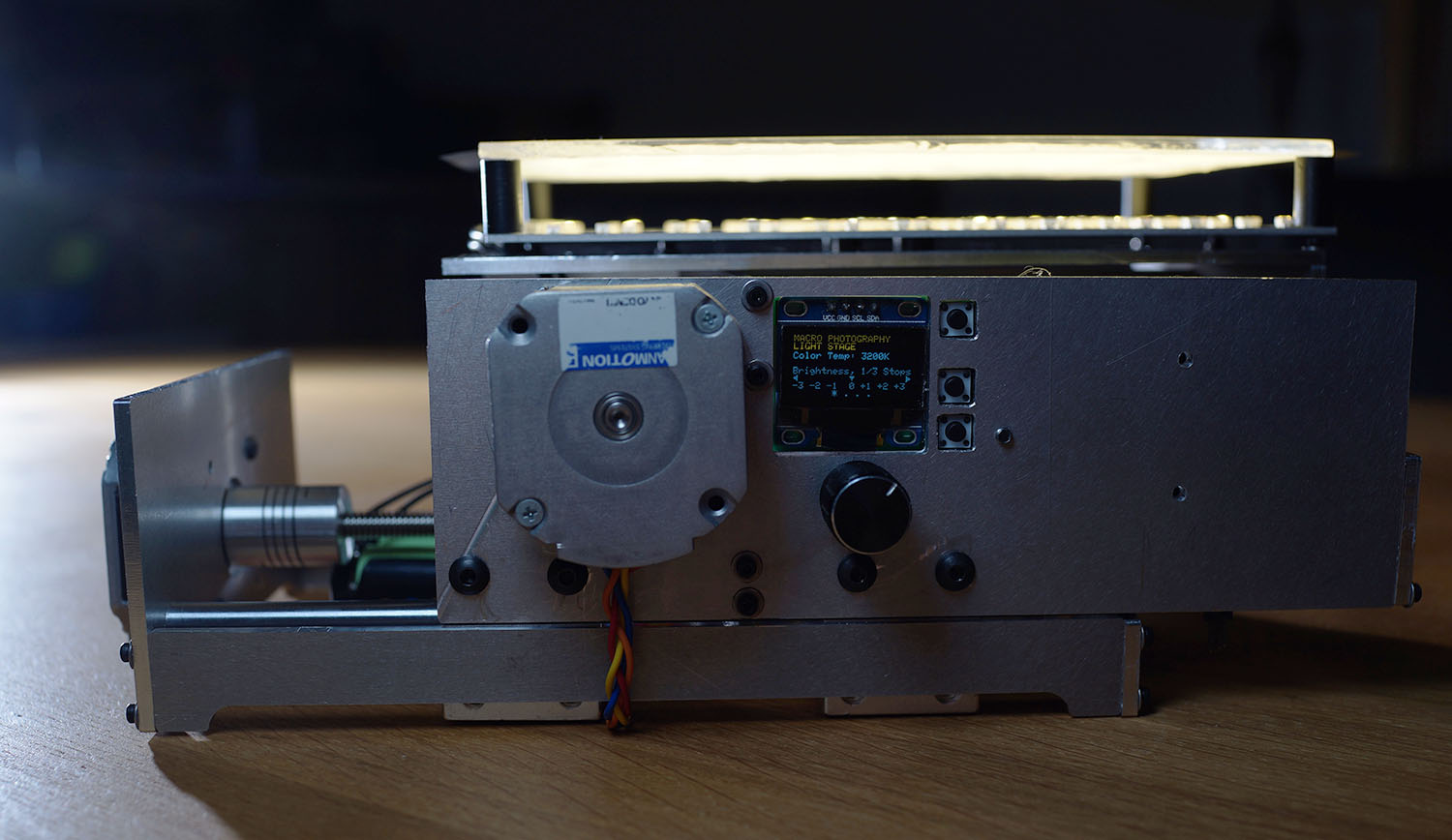
As of 02/01/18 significant progress was made on the software of the system with only some details in mapping light output of the LED light stage remaining unfinished. A physical bread-boarded mock-up currently has much of the required functionality of the final product, albeit without the light stage itself or the mechanical frame. A user is able to interface with the device via a screen, a dial, and three buttons; up, down, and page. The screen shows the information available to be changed. The dial controls the power to the system and the color temperature of the light stage, which is viewed on the main screen. The color temperature is variable in 50K increments from 3200K to 5500K, those being the limits of the two different LEDs. Ticks at the bottom of the screen indicate which page the user is on, as well does the title at the top of the screen. The page button allows the user to change screens with a tap and scroll through page items with a long press. Page items which are selected are indicated by blinking and can be changed with the up and down buttons. Up and down also control the light stage brightness from the main screen and start the raster routine when selected. This brightness is adjusted in 1/3 stops (from -3 to +3 stops) since the stage is intended as a photographic tool. For reference, the maximum light output is projected to be close to 1000 lumens, or ~25,000 lx.
Below is a video of the functionality of the project by 02/01/2018.

Motor Setup
The motor setup is meant to allow the user to adjust the raster parameters for the scan. Row height and column width allow the user to change the movement distance left/right and up/down to match the physical size of the camera sensor being used. At macro 1:1 the image should be the same as that of the camera's sensor. As an example: I use a m4/3 camera with a 17.3mm x 13mm sensor so in order to create images that overlap properly for stitching I would under rate these dimensions by 10-25%. In this case I would set my row height to 11mm and my column width to 15mm if my camera were scanning in landscape.
Scanning images such as film negatives requires a raster of varying row and column amounts. Thus the number of rows and columns are available to change on screen. In order to scan a 35mm negative in landscape using the same m4/3 setup as before we would have to calculate the number of rows and columns as follows: A 35mm negative has a height of 24mm, so to cover the frame height we need to take three of the 11mm steps that we calculated before. The 36mm frame width would also require 3 columns since our 15mm step would only cover 30mm with just 2 images/columns. Conversely the row height and column width could be calculated after determining how many rows and columns are needed; i.e. if we must take at least three images to cover the frame width of the 35mm negative then we could have a column step width of 36mm / 3 = 12mm and therefore make the overlap between images larger for stitching and get rid of the wasted 9mm on the final column's images.

Ultra Resolution Setup
To resolve more detail than is possible with even a high resolution sensor and a macro lens, micro actuation of the light stage can be used to differ images by only factions of a pixel. These tiny movements allow minutely varying images to be produced and interpolations thereof to be created. Slight variations in any single pixel on multiple images can be used to determine detail between these images since we know how they vary in distance.
Pixel 1 may be black in one image and white in another, but since the second image was moved half a pixel to the right we know that there is a change moving from left to right of black to white. If pixel 2 (residing to the right of pixel 1) is white in both images then we know that the transition from black to white occurs somewhere between the positions of pixel 1 in the first image and pixel 1 in the second image. In this way we gain more information about the detail in the image and can therefore place an extra pixel between pixels 1 and 2, expanding the resolution of the image and improving resolvable subject detail.
Design
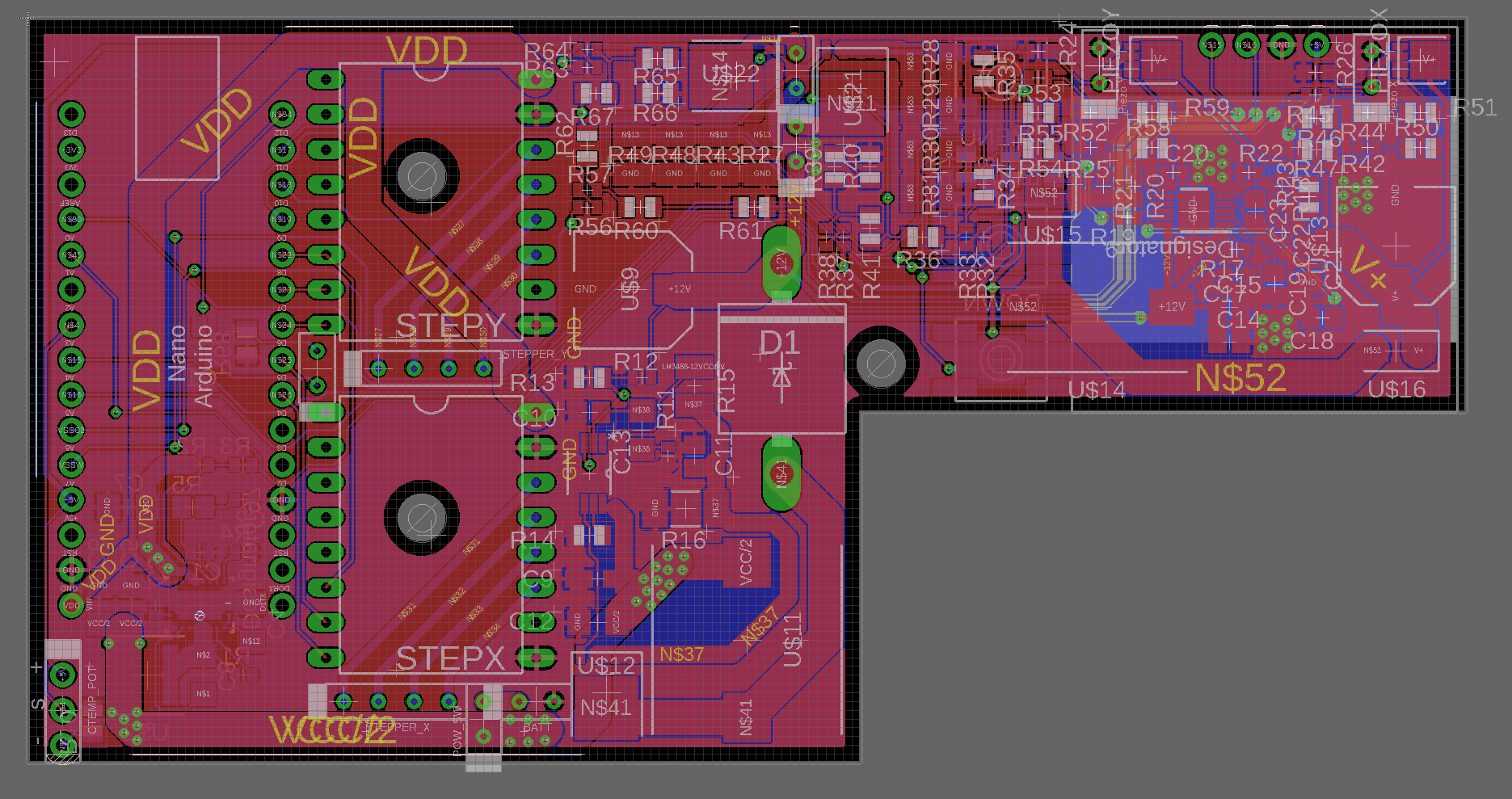
The schematic could be designed without reference to the design of the device itself. Laying out the board would take consideration of physical constraints in the board and light stage.
Six basic blocks needed to be built for the light stage to function as intended. The light stage required a pair of 12V drivers for each set of LEDs; 3200K and 5500K. The X and Y axis motors needed 6V drivers as well did the X and Y piezo actuators need 75V drivers. The motor drivers were purchased as is but the piezo drivers were designed. All components then needed power. The power supply was intended to be a pair of 18650 cell lithium batteries in parallel for high current capacity, portability, and rechargability. This was a poor design decision based on the fact that I did not want to design my own 12V (11.1V) balanced lithium cell charger for fear of it taking up too much space on the board and instead use off-the-shelf USB charger boards. These charger boards are convenient for small projects, but only charge a single series cell. So my power supplies were supplied with 3.7V power. Thus the Arduino needed to be powered from this, as along with the steppers, piezos, and LEDs.
Since the steppers were rated for 6V a boost converter could be used to power both the Arduino (7-12V tolerant) and steppers. Another boost converter could be used for the 12V supply to the LEDs and a final 75V boost converter powered from the 12V bus to supply power to the piezos (easier and cheaper than creating a 3.7V->75V converter). Each of the supplies are shown in the schematic along with the pairs of drivers.
Each of the LED and piezo driver pairs was designed as a simple open loop current controller. They are designed to be simple to construct and easy to use in both smooth and PWM modes. FETs were used to control the output current of the driver, essentially clamping the voltage at the source by changing the gate voltage. A very low impedance was placed after the source to define the current in the circuit. Any voltage from the supply which is not dropped over this shunt is dropped either in the load or in the FET. Thus if the current is forced low and the LEDs are not made to drop much voltage, the residual is dropped over the FET. This is inefficient, but allows the use of the driver in a smooth constant output mode. If the current is forced high then the voltage drop over the LEDs is nearly the supply voltage so very little voltage is dropped over the FET, increasing the driver efficiency. Thus a PWM mode could easily be used to increase the efficiency of the driver while the smooth output could be used to avoid issues with shutter speed.
The driver gate voltage is defined in the spec sheet for the FETs and therefore require some mapping from the 0-5V output of the Arduino to the 1.2-2.5V specified in the sheet. Op-amps are a good application for this since they can easily be used to perform mathematical calculations required for this mapping. However nice a solution this is, op-amps are expensive for such a simple task and are considerably bulky on a board which should be kept as small as possible. Thus a purely passive solution is used in the form of an H-bridge voltage divider. A first voltage divider is used to set the low voltage while a second is used to vary the output. These two dividers are connected together via another higher impedance voltage divider to average the voltages of the two dividers. This average is the output to the FET gate. A 5V reference from the Arduino is divided in the first divider. The second voltage divider is supplied by an analog output of the Arduino so that if the input is 0V the average of the two dividers is 1.2V and 2.5V on a 5V input. The piezo drivers are deigned similarly.
By the end of the May, 2018 the stage was completed. The physical design including the PCB were completed and sent for manufacture. In fact there were two separate PCBs to make, the main controller board and the light stage itself. Eagle had recently had linking functionality with Fusion 360 so it was used instead of a free software such as Ki-CAD. Since I had been wanting to learn Fusion for a while and decided to use this project as a means to do so. I needed to design the stage alongside the circuit boards since space needed to be reserved to fit in the electronics in a reasonable spot within the device. Some off-the-shelf components were used such as the Arduino Nano board and daughter boards for the stepper motor controllers. This increased the footprint of the electronics since mounting headers needed to be accounted for. Below are renders of the device in Fusion. The X and Y axes are visible as separate movable layered sections which attach to a base and carry the top plate, i.e. the stage itself. The ACME screws are visible from the top view while the screen, buttons and control knob area visible from the front.
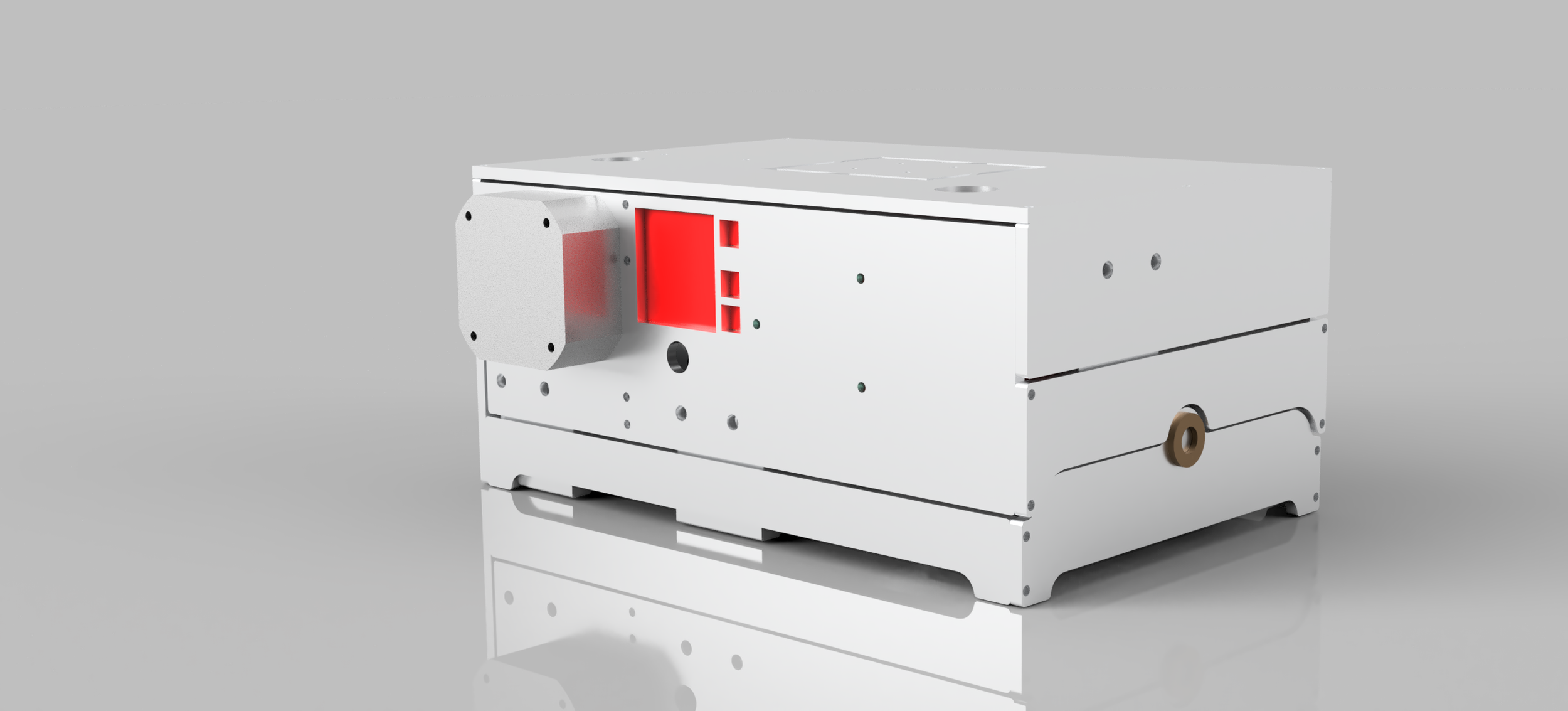
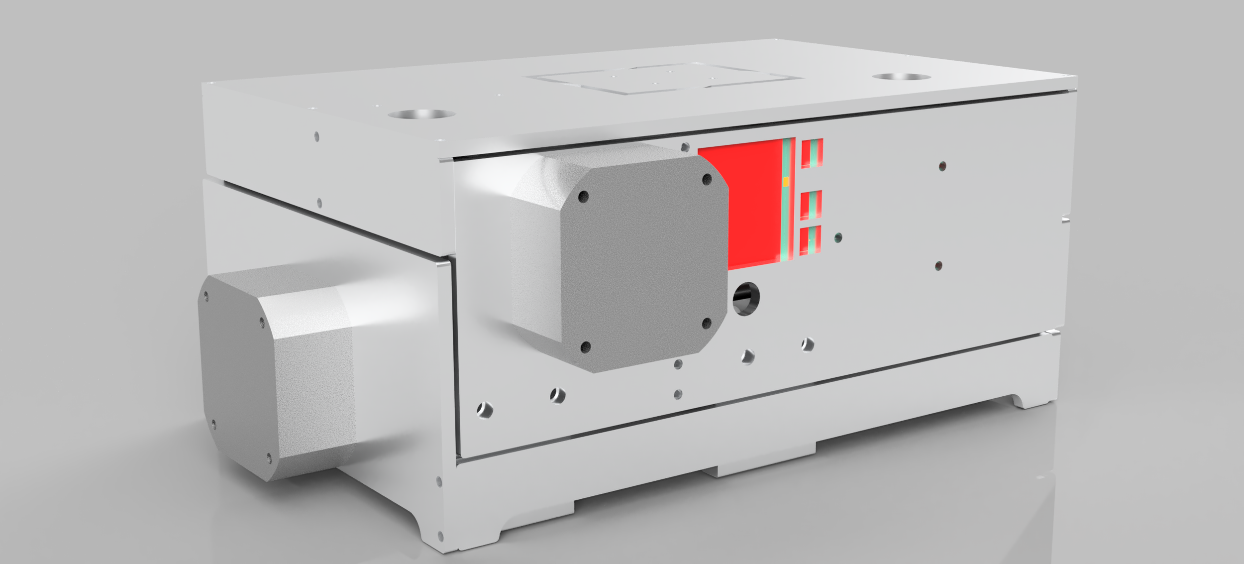
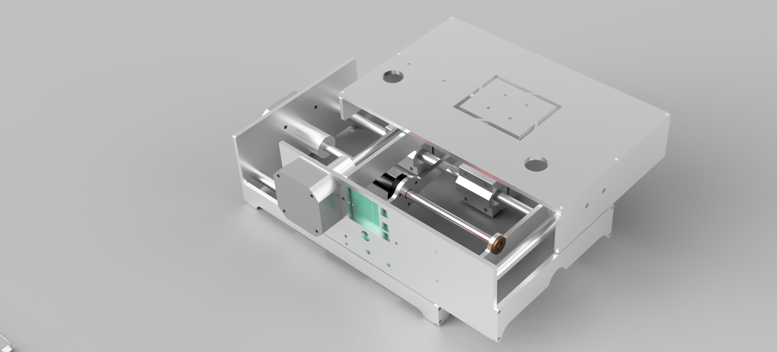
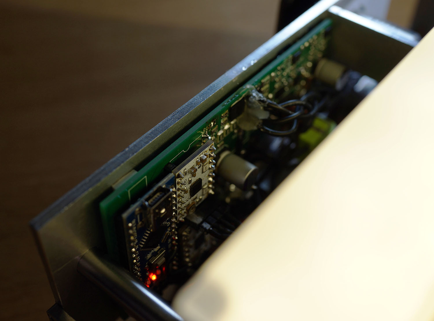
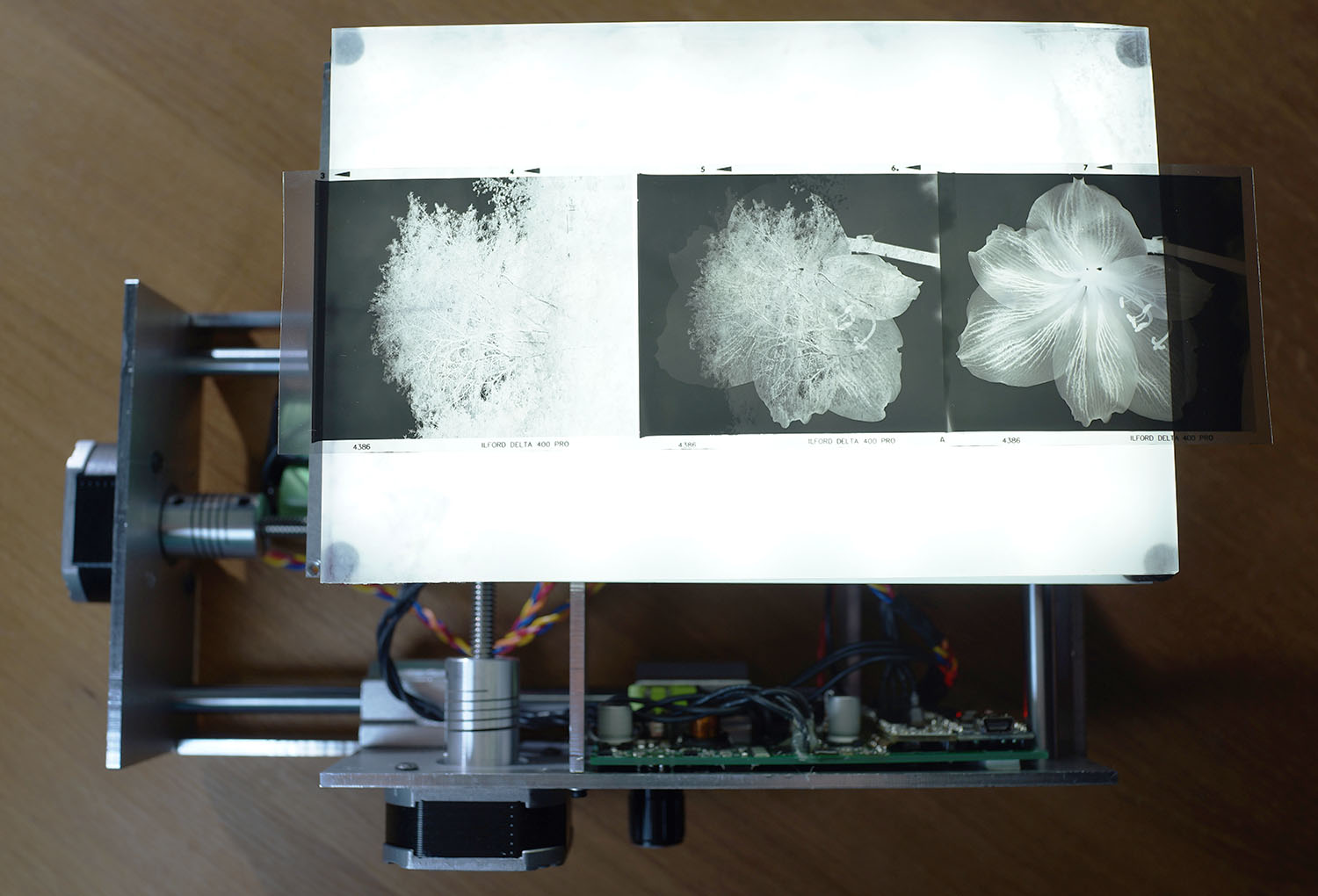
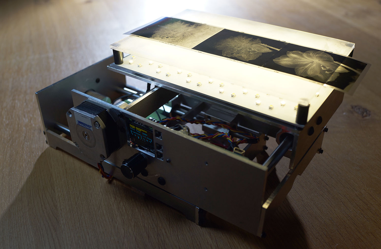
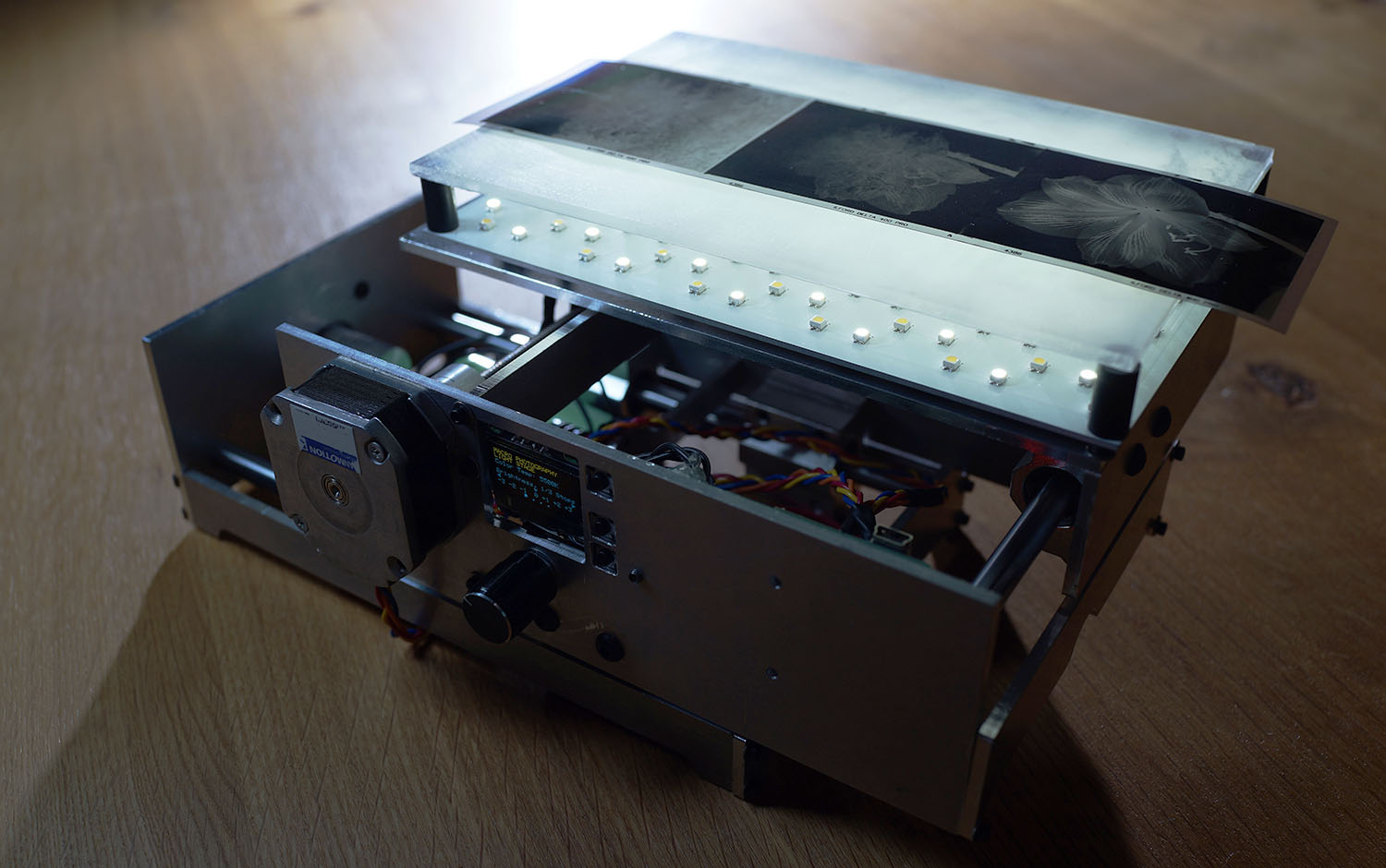
The pieces of the body were CAMed in Fusion and routed out of aluminum flat stock on a CNC machine. Bushings, bearings, motors, and supports were assembled in the routed pieces. The aluminum pieces had been drilled and tapped to fasten the structure together and retain all the mechanisms. Once the boards were received from manufacture, they were populated and attached to the interior of the body. The screen and buttons are visible through the holes in the front plate next to the Y-axis stepper motor. The LED sets are visible on the aluminum PCB. Two images bellow show the light set to 3200K and 5500K to illistrate the the color change and the different sets of LEDs.

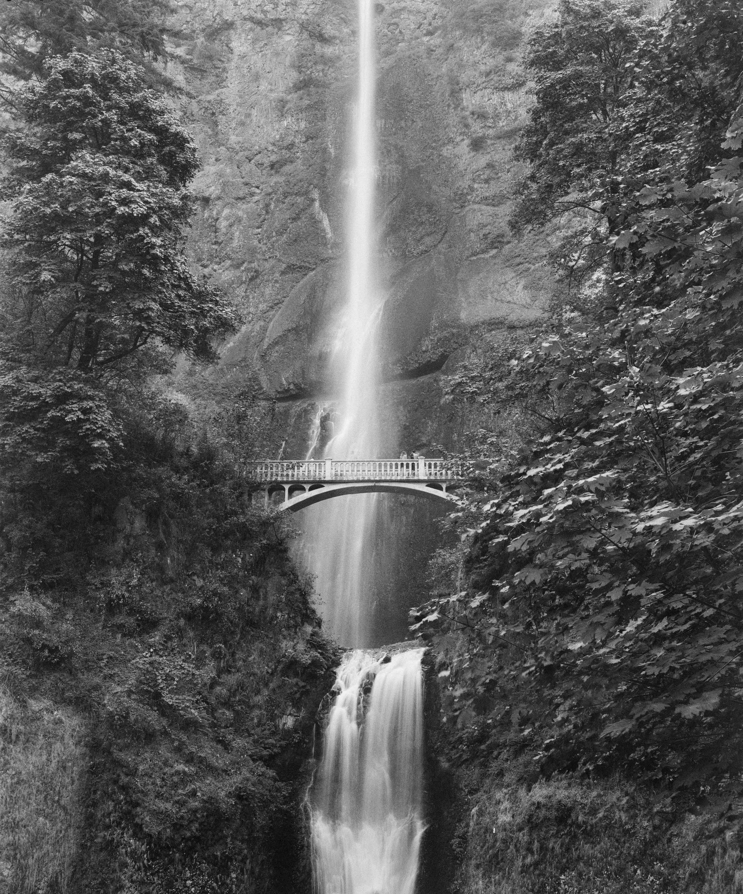
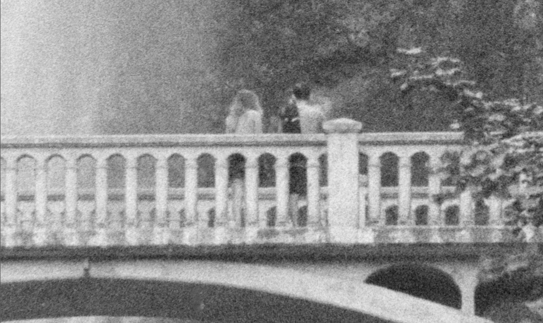
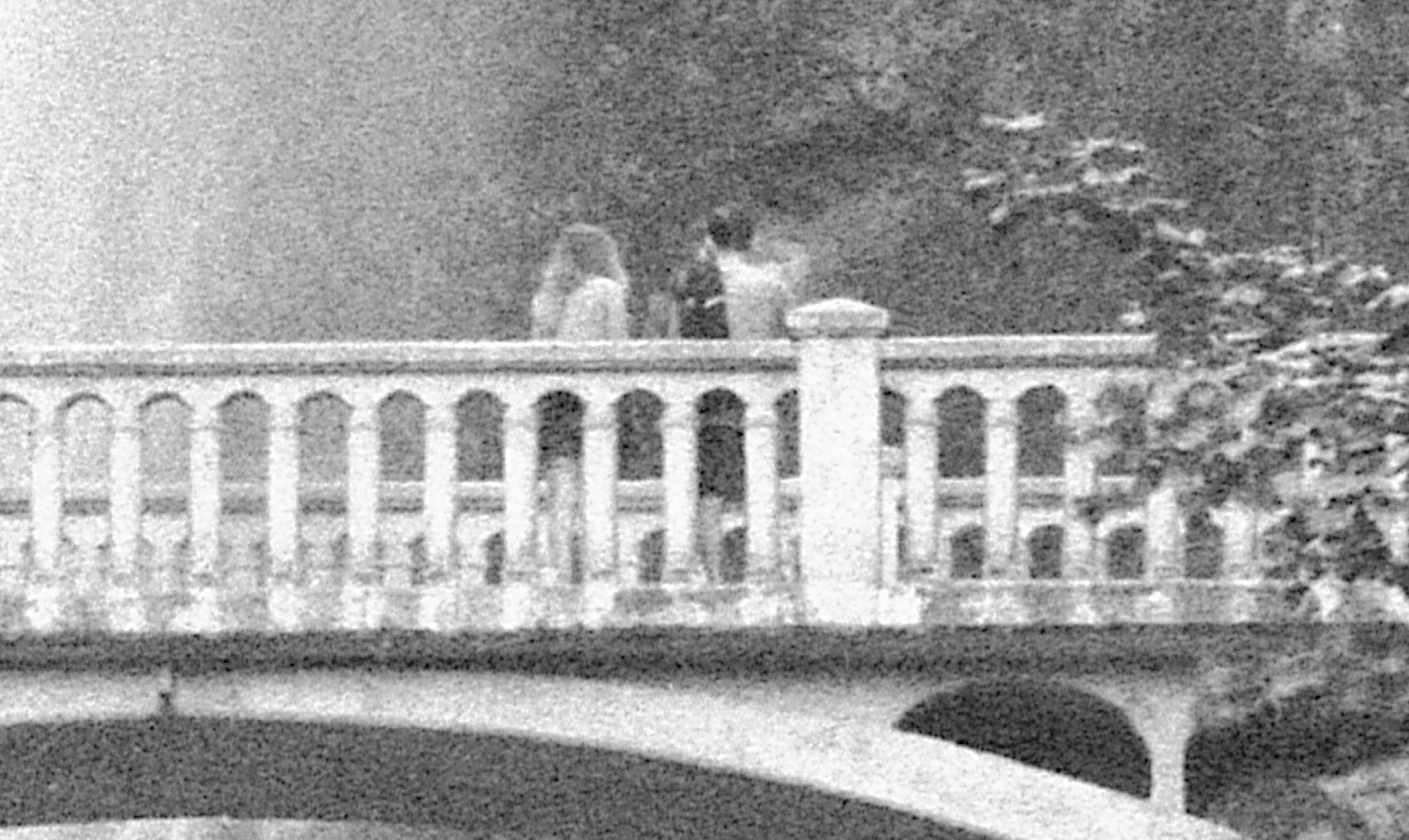
Results
Many improvements could be made in future versions. Empirical measurements are difficult to obtain for verification of the color temperature and light emission of the stage, so these measurements were best approximated by taking photographs of the stage and manually adjusting the camera settings in the opposite direction, looking for similar photo outputs. Function of the UI was predominantly verified during software development and continued to work during this stage. The movement of the steppers and their rastering pattern provided very accurate positioning for the camera to capture image sets which were later processed and stitched. Outputs from a good consumer grade flatbed scanner (Epson V700) and the MPLS are shown below. Results are no worse than a flatbed scanner and take less time to capture. Furthermore, images can be captured in RAW format and converted into Digital Negatives, retaining more information for processing than the TIFF output of the scanner. This also does not require the difficult preprocessing setup of the scanner, rather only a rough setup of familiar camera settings. MPLS also allows other scans and photographs of other subjects which flatbed scanners cannot handle. Ultraresolution Imaging verification is difficult due to the very small associated movements and blending software being the most important verification factor. Further developments on this topic will come in future.